Astable 555 Timer Schematic : rOmV4 - Timing 555 Astable : Jan 13, 2016 · the standard 555 astable circuit has a minimum duty cycle of 50%.
byAdmin•
0
Astable 555 Timer Schematic : rOmV4 - Timing 555 Astable : Jan 13, 2016 · the standard 555 astable circuit has a minimum duty cycle of 50%.. As the name specifies, a monostable multivibrator has only one stable state. This is the basic mode of operation of the ic 555. If you are driving an led by pulling it's anode end up to (approx.) vcc, you cannot get a short blink followed by a longer off time without a trick. That is, the output always is high longer than it is low. In this circuit, we will connect the 555 timer to be in astable mode.
Jun 16, 2015 · the following figure is the schematic of ic 555 as a monostable multivibrator. The connections are shown below. Create a new project by clicking file>new>project give that project a descriptive name (e.g. In this mode, the 555 timer will go from high to low, high to low, high to low. That is, the output always is high longer than it is low.
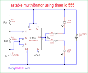
astable multivibrator using timer ic 555 - theoryCIRCUIT ... from theorycircuit.com In this mode, the 555 timer will go from high to low, high to low, high to low. As the name specifies, a monostable multivibrator has only one stable state. We will be running it in astable mode , which produces a square wave on the output pin. That is, the output always is high longer than it is low. Jan 13, 2016 · the standard 555 astable circuit has a minimum duty cycle of 50%. This is the basic mode of operation of the ic 555. It requires only two extra components to make it work as a monostable multivibrator: If you are driving an led by pulling it's anode end up to (approx.) vcc, you cannot get a short blink followed by a longer off time without a trick.
Sep 11, 2019 · 555 ic circuits (96) 741 ic circuits (18) amplifiers (54) arduino engineering projects (82) audio projects (87) battery chargers (80) car and motorcycle (90) datasheets (46) decorative lighting (diwali, christmas) (32) diy led projects (84) electronic components (97) electronic devices and circuit theory (35) electronics tutorial (104) fish.
The connections are shown below. As the name specifies, a monostable multivibrator has only one stable state. In this circuit, we will connect the 555 timer to be in astable mode. If you want to know all the pinout of the 555 timer, what each pin is and what each pin does, see 555 timer pinout. A transistor could be used if needed. Create a new project by clicking file>new>project give that project a descriptive name (e.g. A resistor and a capacitor. It requires only two extra components to make it work as a monostable multivibrator: That is, the output always is high longer than it is low. If you are driving an led by pulling it's anode end up to (approx.) vcc, you cannot get a short blink followed by a longer off time without a trick. The 555 timer is a simple chip that has all sorts of uses. This is the basic mode of operation of the ic 555. Feb 26, 2017 · i need a 555 timer circuit that, when power is applied, will turn on an led for five minutes and then start blinking the led continuously at 1 second intervals.
It requires only two extra components to make it work as a monostable multivibrator: This is the basic mode of operation of the ic 555. I was wondering if this can be done using a single 555 timer? Jan 13, 2016 · the standard 555 astable circuit has a minimum duty cycle of 50%. In this circuit, we will connect the 555 timer to be in astable mode.
'555' Astable Circuits | Nuts & Volts Magazine from www.nutsvolts.com In this mode, the 555 timer will go from high to low, high to low, high to low. It requires only two extra components to make it work as a monostable multivibrator: Feb 26, 2017 · i need a 555 timer circuit that, when power is applied, will turn on an led for five minutes and then start blinking the led continuously at 1 second intervals. I was wondering if this can be done using a single 555 timer? Jan 13, 2016 · the standard 555 astable circuit has a minimum duty cycle of 50%. If you are driving an led by pulling it's anode end up to (approx.) vcc, you cannot get a short blink followed by a longer off time without a trick. In this circuit, we will connect the 555 timer to be in astable mode. We will be running it in astable mode , which produces a square wave on the output pin.
If you want to know all the pinout of the 555 timer, what each pin is and what each pin does, see 555 timer pinout.
In this mode, the 555 timer will go from high to low, high to low, high to low. This is the basic mode of operation of the ic 555. Create a new project by clicking file>new>project give that project a descriptive name (e.g. Sep 11, 2019 · 555 ic circuits (96) 741 ic circuits (18) amplifiers (54) arduino engineering projects (82) audio projects (87) battery chargers (80) car and motorcycle (90) datasheets (46) decorative lighting (diwali, christmas) (32) diy led projects (84) electronic components (97) electronic devices and circuit theory (35) electronics tutorial (104) fish. Feb 26, 2017 · i need a 555 timer circuit that, when power is applied, will turn on an led for five minutes and then start blinking the led continuously at 1 second intervals. Jun 16, 2015 · the following figure is the schematic of ic 555 as a monostable multivibrator. The connections are shown below. A transistor could be used if needed. If you want to know all the pinout of the 555 timer, what each pin is and what each pin does, see 555 timer pinout. That is, the output always is high longer than it is low. We will be running it in astable mode , which produces a square wave on the output pin. A resistor and a capacitor. It requires only two extra components to make it work as a monostable multivibrator:
The 555 timer is a simple chip that has all sorts of uses. Jan 13, 2016 · the standard 555 astable circuit has a minimum duty cycle of 50%. Create a new project by clicking file>new>project give that project a descriptive name (e.g. This is the basic mode of operation of the ic 555. In this mode, the 555 timer will go from high to low, high to low, high to low.
Tishitu (Tutorial Proteus 555 Timer Astable Multivibrator ... from ctn-2011.e-monsite.com Feb 26, 2017 · i need a 555 timer circuit that, when power is applied, will turn on an led for five minutes and then start blinking the led continuously at 1 second intervals. Jan 13, 2016 · the standard 555 astable circuit has a minimum duty cycle of 50%. As the name specifies, a monostable multivibrator has only one stable state. Sep 11, 2019 · 555 ic circuits (96) 741 ic circuits (18) amplifiers (54) arduino engineering projects (82) audio projects (87) battery chargers (80) car and motorcycle (90) datasheets (46) decorative lighting (diwali, christmas) (32) diy led projects (84) electronic components (97) electronic devices and circuit theory (35) electronics tutorial (104) fish. It requires only two extra components to make it work as a monostable multivibrator: This is the basic mode of operation of the ic 555. The connections are shown below. Create a new project by clicking file>new>project give that project a descriptive name (e.g.
Sep 11, 2019 · 555 ic circuits (96) 741 ic circuits (18) amplifiers (54) arduino engineering projects (82) audio projects (87) battery chargers (80) car and motorcycle (90) datasheets (46) decorative lighting (diwali, christmas) (32) diy led projects (84) electronic components (97) electronic devices and circuit theory (35) electronics tutorial (104) fish.
We will be running it in astable mode , which produces a square wave on the output pin. Feb 26, 2017 · i need a 555 timer circuit that, when power is applied, will turn on an led for five minutes and then start blinking the led continuously at 1 second intervals. It requires only two extra components to make it work as a monostable multivibrator: The 555 timer is a simple chip that has all sorts of uses. If you are driving an led by pulling it's anode end up to (approx.) vcc, you cannot get a short blink followed by a longer off time without a trick. I was wondering if this can be done using a single 555 timer? In this mode, the 555 timer will go from high to low, high to low, high to low. Create a new project by clicking file>new>project give that project a descriptive name (e.g. If you want to know all the pinout of the 555 timer, what each pin is and what each pin does, see 555 timer pinout. Jun 16, 2015 · the following figure is the schematic of ic 555 as a monostable multivibrator. This is the basic mode of operation of the ic 555. A resistor and a capacitor. A transistor could be used if needed.
Feb 26, 2017 · i need a 555 timer circuit that, when power is applied, will turn on an led for five minutes and then start blinking the led continuously at 1 second intervals 555 timer schematic. This is the basic mode of operation of the ic 555.